Rotary dryer operation manual
This is an operation manual for most rotart dryer, they may some differences on detail applicated dryer, so the article just as an reference, for detail manual, please contact us.
1.Introduction
The drying of raw materials (including clay, sludge, fly ash, raw coal, limestone, sand, or mixed materials, etc.) is an important part of the production process of building materials enterprises, and energy conservation and consumption reduction are the primary problems to be solved in the drying process.
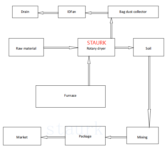
2.Flow chart
3.Working principle
The main body of the rotary dryer is a rotary cylinder with a certain slope, equipped with fuel chamber, exhaust, dust collection, feeding device, etc. It uses high-temperature flue gas as the drying medium and enters the drying drum under the suction of the exhaust device. Wet materials enter the dryer drum through the feeding device and come into contact with high-temperature flue gas. High temperature flue gas transfers heat to wet materials through convection, radiation, and conduction, which is a heat transfer process. After the material is heated, water evaporates into the drying medium, which is a mass transfer process. During the process of heat and mass transfer, the material constantly moves due to the continuous rotation of the cylinder. The material flows from the high end to the low end of the cylinder, and the gas is also driven by the exhaust to flow from the high pressure to the low pressure. During the movement of gas and material, the material is dried and discharged outside the machine, and the exhaust gas is discharged to the atmosphere after dust collection.
4.Installation and debugging
4.1Preparation before installation
1. Prepare a layout plan for foundation and anchor bolts.
2. Prepare drawings of tire and idler design dimensions and adjustment points.
3. Equipped with transmission layout diagram and reference data for large and small gears.
4. Thoroughly clean the surface of the base, clean and lubricate the adjusting screws to facilitate the adjustment work.
5. Clean and dispatch the oil sludge and dirt between the crossbeam of the supporting wheel base for measurement work at the supporting wheel.
6. Clean the gears and gear covers.
Before installation, it is necessary to verify the dimensions according to the drawings, especially the elevation, center distance, slope, and position of the anchor bolt holes
It is necessary to verify the actual dimensions of the equipment. If the physical object does not match the drawing and affects the installation dimensions, the basic dimensions should be taken into account,
Correction will be made as the final installation basis.
4.2 Installation process and quality control
The installation of the dryer starts with the main unit, followed by the installation of the inlet and outlet devices and other components.
4.2.1. Basic marking
Firstly, draw a horizontal foundation line on the side of the foundation and embed high plates at the four corners of the foundation, with an elevation error of no more than 0.5mm.
Draw the longitudinal centerline at the same time, with a tolerance of no more than 0.5mm. Based on the revised final installation data, on a horizontal basis,
Set the horizontal centerline of the foundation, with a center to center error of no more than 1.5mm between the two foundations.
4.2.2. Installation of support device
(1) On the machined surface of the base, mark the longitudinal and transverse centerlines based on the anchor screw holes for installation and alignment.
The installation of supporting devices must be carried out when the concrete foundation strength reaches 75% or above.
(2) To ensure that the inclination of the cylinder body meets the requirements after installation, it is mainly necessary to ensure the accuracy of the standard deviation of the high and low wheel seat foundations. The height of this mark can be found from the drawing. The following equation can be used to indicate:
Elevation difference=center distance between two wheels (mm) × inclination (%)
(3) After the base installation is completed and accurately aligned, the following requirements must be met:
The error between the cross centerline of the supporting wheel base and the centerline (or center elevation) of the design position shall not exceed ± 2mm; The longitudinal centerlines of the two bases must be on the same straight line, with an error not exceeding ± 0.5mm; The elevation error of two sets of supporting wheels shall not exceed 1mm, and the elevation of two supporting wheels in the same set must be consistent, with an error of ± 0.1mm; The lateral center error of the two sets of supporting wheels shall not exceed ± 0.3mm; The slope of the supporting wheel should be in accordance with the specifications on the drawing, and its error should not exceed ± 0.1mm/m.
(4) Assemble the supporting wheel axle onto the base and adjust it to meet the following requirements:
The two wheels on the high-end rim side should be in the same plane and can be checked with a ruler, with an allowable error of 0.5mm;
The distance between the longitudinal centerline of the two wheels and the longitudinal centerline of the base should be equal to and comply with the dimensions on the drawing, with an allowable error of 0.5mm;
Check the surface inclination of each supporting wheel using a slope gauge, which should be consistent and the allowable error should not exceed 0.5mm/m when the allowable error is exceeded, a shim plate can be added under the bearing base to adjust it;
Require the use of a theodolite to check that the top of all supporting wheels is located within an inclined plane X% of the horizontal. If the elevation or inclination
If there is an error in the slope, it should be adjusted by slightly raising or lowering the base until it is completely correct.
(5) After the supporting device meets the requirements, a mark should be made on the base facing the center of the supporting wheel support for future maintenance Or adjust the basis during operation.
(6) Grouting of foundation screw holes
After the installation and correction of the foundation, the foundation grouting should be carried out. Only after the concrete strength increases can the foundation screws be tightened.
(7) Secondary grouting
Secondary grouting should be carried out between the foot and the foundation. Before grouting, tighten the foot screws, tighten the diagonal iron, and use electric welding to secure the pad iron. However, the base and pad iron cannot be welded together. The foundation under the base should be cleaned thoroughly, and the grouting should be compacted without any gaps or honeycomb defects.
4.2.3. Cylinder and gear wheel
(1) Timely inspection of the cylinder body
a) Before hoisting and dismantling the cylinder support, the ellipticity of each section of the cylinder should be checked, and the ellipticity should be controlled within below 0.2% D, otherwise the internal support channel steel must be removed and corrected on a mutually perpendicular straight line using a jack and adjusting screws.
b) The cylinder must be inspected before welding, with a misalignment of no more than 2mm, and the end face perpendicular to the centerline of the cylinder the degree should not exceed 2mm, and the rust, oil stains, and other impurities on the weld groove should be thoroughly removed to achieve smoothness and cleanliness.
4.2.4. Transmission device
Before installation, the installation dimensions of the components should be checked. If they do not match the design, the installation dimensions should be corrected, including all shafts and reducers
The machine should be cleaned thoroughly and immediately coated with the lubricating grease specified in the design.
The weld seam of the outer cylinder at the installation of the large gear ring must be smoothed with a grinding wheel, and its width should be 100mm wider than the width of the spring plate.
The installation of the large gear should be carried out after the cylinder is installed in place. The method is to first manufacture auxiliary tools with left and right threaded screws four sets, evenly distribute the tools on the circumference of the cylinder and spot weld them to temporarily fix the large gear. Wrap a steel wire rope around it on the cylinder, pull the steel wire rope, rotate the cylinder, adjust the nut on the auxiliary tool, calibrate the large gear to make it radial and end wise
The surface jumping is within the allowable range, then drill rivet holes, tighten them with screws after drilling, and then rivet the rivets in sequence. use when welding the spring plate, align it and directly weld it to the cylinder. After riveting, remove the auxiliary tools. Require radial gear ring the circular runout is greater than 1.5mm, and the circular end runout of the end face is not greater than 1mm.
Pay attention to the relationship between the spring and the direction of rotation, and ensure that the spring plate is subjected to tensile force during operation.
When installing the transmission device base, its horizontal position should be determined based on the centerline of the cylinder, and the surface elevation should be supported by a pulley the surface elevation of the supporting device is based on the standard, and the height difference is determined by marking the design dimensions. The surface slope and requirements are consistent with those of the supporting wheel base same.
The installation of the small gear is determined by the center of the large gear to determine its axial position. After the installation of the small gear, the following requirements should be met requirement:
a) At any angle during one revolution of the large gear ring in the cold state, the clearance between the tooth tips of the large and small gears shall not be less than 0.25M (M is the gear module).
b) Check the contact condition of the tooth surface, and ensure that the contact spot is not less than 40% along the tooth height direction and not less than 50% along the tooth width direction
c) The low-speed shaft of the reducer should be concentric with the gear shaft, with a coaxiality tolerance of 0.2mm. The horizontal and vertical slopes of the reducer should be measured on the machined joint surface of the reducer housing, with an allowable error of ± 0.05mm/m.
The axial relative position deviation between the large gear ring and the small gear ring shall not exceed ± 2mm.
5. Trial test operation
1. The trial operation requires checking whether there is any change in the foundation elevation, whether the connecting bolts and anchor bolts at all locations are tightened, and whether the lubrication points are adequately lubricated according to the specified brand. Before starting the drying process, check if there is anything stuck or interfering with the rotating parts. Wait until everything is checked and confirmed to be correct before conducting a trial run.
2. Before the trial operation of the entire dryer, each individual machine must be tested, with the motor running for 2 hours without air and the reducer running for 4 hours. Check and record the current, temperature rise, lubrication situation, and pay attention to whether the sound is normal.
3. The continuous no-load operation time of the entire dryer shall not be less than 8 hours. After 48 hours of load operation, the following checks are required:
(1) Check for any vibration, impact, or abnormal noise, ensure proper meshing and contact of the large and small gears, the motor load should not exceed 30% of the rated power, the temperature rise should not exceed 40 ° C, and the current should not exceed its rated value.
(2) Whether the surface of the tire and the supporting wheel are in uniform contact, and the contact length shall not be less than 70%.
(3) Whether the sealing device of the cylinder maintains good contact during operation and there should be no local friction phenomenon.
(4) Check for any looseness in the connecting bolts and tighten all bolts again, especially the matching bolts of the large gear ring, the fixing bolts of the stop wheel, the sealing bolts of the inlet and outlet ends of the cylinder, as well as the fixing bolts of the upward feeding plate and spiral blades of the cylinder.
6.Maintenance and repair
6.1Driving operation and parking
1. Before driving, it is necessary to carefully inspect all parts of the hot air stove and dryer to confirm that they are correct before starting.
2. Do not operate the dryer in the following situations:
(1) The reserve of raw materials cannot guarantee the continuous operation of the dryer for a certain period of time.
(2) There is looseness in the connections of various parts, and there is abnormal vibration, noise, impact, and movement in the support and transmission devices.
(3) Before igniting the hot blast stove, the ventilation equipment was not turned on.
(4) Before starting the dryer, preheat the machine body with hot air first, and then feed from less to more until normal.
Before parking, first stop the hot air from entering the dryer and then stop feeding. Open the cold air door and let the dryer continue to operate. Continue to exhaust until there is no material discharged from the outlet. Only when the exhaust gas temperature is below 45 ° C can the dryer, exhaust fan, and unloading equipment be stopped.
6.2 Maintenance of dryer
1. It is necessary to ensure that the axis of the supporting wheel is parallel to the centerline of the cylinder
Regularly observe and understand the operation status of the idler, determine the contact between the idler and the tire belt, the tire belt and the stop wheel, and the position of the cylinder (i.e. the upper end is located between the two stop wheels). When installing a dryer or conducting regular inspections, as long as the surface of the supporting wheel is smooth and flat, a wire with a diameter of about 2mm can be used to roll between the wheel belt and the supporting wheel. If the lead wire pressed out is a rectangular strip of equal width, it indicates that the axis of the supporting wheel is parallel to the centerline of the cylinder. According to the width of the lead wire pressed out by the left and right supporting wheels, the force on each supporting wheel can be determined. For supporting wheels with excessive force, they should move parallel away from the centerline of the cylinder. Otherwise, they should move parallel to the centerline of the cylinder. To prevent the cylinder from sliding down, the supporting wheel group near the stop wheel can be tilted in a certain direction (the tilting supporting wheel group is made by using a supporting device to thread its two bearings to move equally in opposite directions, and the tilt angle of the supporting wheel should not be too large, with a maximum tilt angle of no more than 30 °, to avoid quickly grinding the supporting wheel group into irregular shapes), so as to generate a force to push the dryer upwards until the cylinder reaches equilibrium, so that the upper end belt is between the two stop wheels. When adjusting the inclined support wheels, it is not allowed to have one gear and two support wheels arranged in an "eight" shape. On the pipe support wheel, the upper support wheel is used as the control wheel. When the cylinder slides down and the wheel belt reaches the lower stop wheel, diesel can be poured on the control wheel to increase the friction between the wheel belt and the support wheel surface. It is not allowed to sprinkle sand on the support wheel to increase the friction between the wheel belt and the support wheel, causing the cylinder to move up. When the cylinder moves up to the point where the wheel belt touches the upper stop wheel, oil can be poured on the control stop wheel to reduce the friction between the wheel belt and the support wheel, causing the cylinder to slide down. It is best to move the cylinder up and down every shift to achieve uniform wear between the wheel belt and the support wheel, thereby improving the service life of the support wheel and the wheel belt.
2. The transmission, support, and gear wheel devices must be regularly inspected, and any abnormal conditions such as noise, vibration, and heating should be promptly addressed.
3. Determine the gap and wear condition based on the relative displacement between the tire and the pad during one rotation, and pay attention to whether there are cracks in the pad weld.
4. Check the foundation bolts and other connecting bolts of the transmission base and supporting parts once per shift, and tighten them promptly if they are loose.
5. Pay attention to whether there is any vibration or sinking phenomenon in the foundation.
6. Check the wear and contact condition of the sealing device.
7. Observe the wear, looseness, and dropping of heat-resistant materials and lifting plates inside the cylinder.
8. Carefully check the sound of the reducer twice per shift to ensure there are no abnormal noises or noises.
9. Maintenance and operation personnel should closely cooperate and strengthen communication.
10. Lubrication of the dryer.
(1) Lubricants should be used according to regulations, and when using substitutes, they must meet the requirements of the specified oil quality performance. It is absolutely not allowed to mix oil and grease for use.
(2) The new dryer should run continuously for 400-500 hours. After the gears are engaged, all the oil should be poured out, and the oil tank should be cleaned before replacing with new oil. From now on, the reducer and large and small gears should be replaced with new oil every 6 months. The replaced waste oil can be mixed with new oil after careful filtration and without deterioration.
(3) The amount of oil added to the reducer should be based on the depth at which the high-speed gear is immersed in the oil, which is 1-3 times the full tooth height.
(4) Check the oil level once per shift. If the oil level drops to the lower limit of the indicator scale, it must be immediately refilled to the upper limit of the oil level indicator.
(5) When oil leakage is discovered, immediate measures should be taken to eliminate the cause of the oil leakage, and it is not allowed for the oil leakage to flow onto the foundation and corrode it.
6.3 Maintenance of dryer
Maintenance work is divided into minor repairs, medium repairs, and major repairs. A plan for major, medium, and minor repairs should be developed based on the usage and maintenance of the dryer.
1. When the tooth thickness of the transmission gear is worn by 30% or 0.5 modulus, or when the wheel rim has irreparable damage, it needs to be replaced or repaired.
2. When there are cracks and local deformations in the cylinder, repair and replacement are required.
3. When the surface of the tire is worn into a cone, polygon, or when there are local through cracks, it needs to be replaced.
4. When the diameter of the supporting wheel axle is reduced by 20% or the thickness of the supporting wheel and the edge roller is reduced by 25%, or the wheel rim is ground into a conical shape or other irregular shape, or there are through cracks in the wheel rim, it must be replaced and repaired
5. The lifting plate needs to be replaced after severe wear and loss of shape.
Debugging and acceptance are the final stages of equipment maintenance, and they are the most comprehensive inspection steps for the quality of maintenance projects. The expected purpose of maintenance work is achieved when the equipment operates under heavy load conditions and the load conditions meet the specified technical requirements.
7. Precautions
1. Any maintenance work must be carried out after parking and a "Do Not Drive" sign must be hung on the motor switch.
2. During operation, it is not allowed to use hands or other objects to probe into the interior of bearings, reducers, or large gear covers for any repair, inspection, or cleaning work, and safety protection facilities cannot be removed.
3. Do not use a cloth tied to your hands or fingers to clean the surface of the rotary machine near it, and be careful not to wrap the wiping material around the rotary machine.
4. Maintenance tools and parts must not be placed on rotating components, especially on pulleys.
5. Work clothes should be tightly fastened to avoid personal accidents caused by mechanical parts twisting the sleeves.
8. Other instructions
1. This finished product should be protected against corrosion and rain during transportation and storage, as well as mechanical damage and deformation.
2. Our company provides long-term supply of spare parts and accepts customer commissions to undertake major repair services. If we entrust our company to repair, we need to provide usage and maintenance information and records, and jointly develop a major repair plan.
Related:


Send Message
Please write down your requirement and contact details in the following form. You can also send a message to us by this email sales@staurk.com, we will reply to you within 24 hours.